DIY CPU-Controlled Traffic Light
We thank you for your attention!
Microcontrollers can do almost anything. They are built from logic gates, flip-flops, counters, bus drivers, and other basic digital building blocks. That means you can also build a computing device for a specific job using those same building blocks as separate ICs.
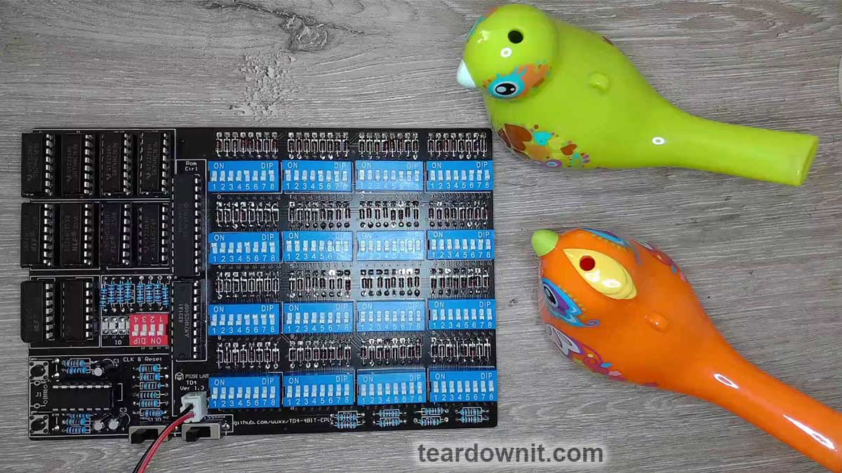
I’ve already built a 4-bit microprocessor from twelve discrete logic ICs. It worked, and I even ran programs on it!
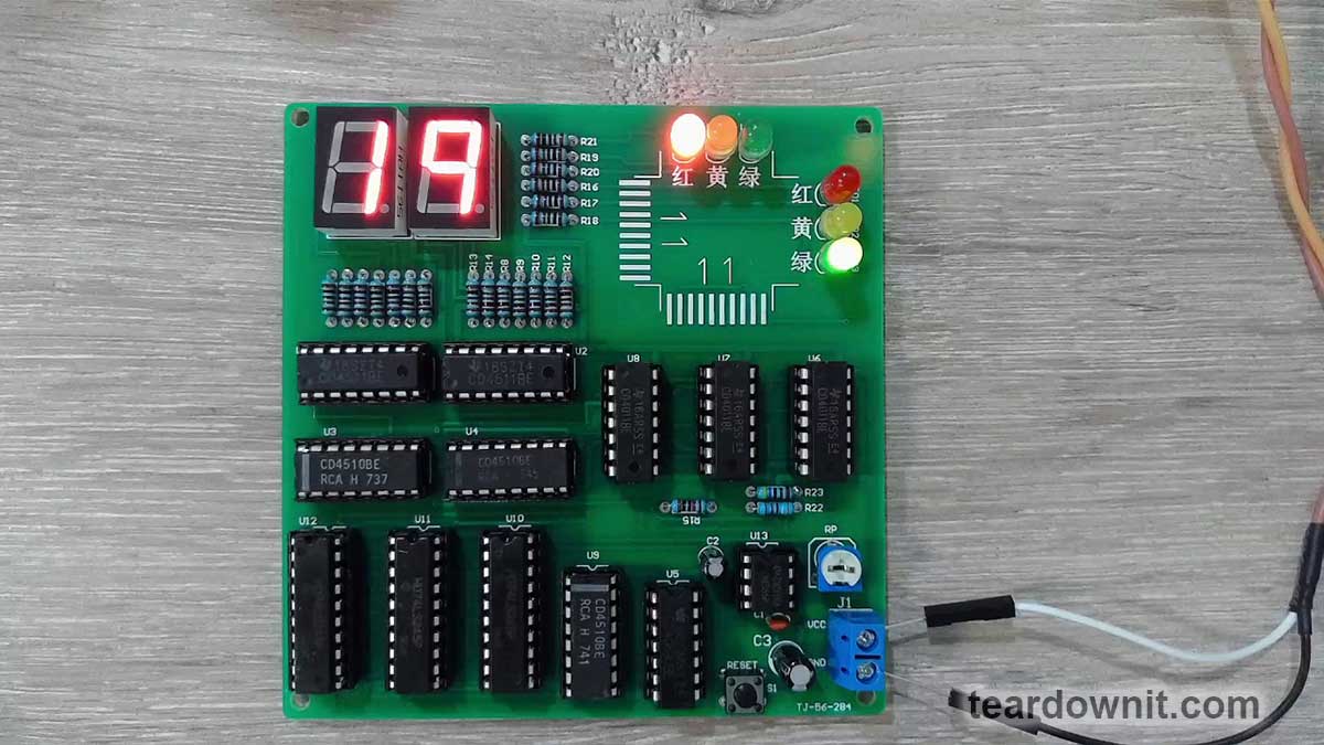
Today’s traffic light controller also uses twelve ICs plus a clock generator, and it implements several functions you would normally associate with a computer.
It has a clock counter that plays a role similar to an address register: its value determines which stored instruction code is selected for the processor logic.
There is also a circuit that generates the instruction code according to the current counter state. You can think of it as a simple form of read-only memory (ROM).
That binary code is then processed by an instruction decoder, one of the basic building blocks of any microprocessor.
The resulting control signals are sent to the input/output (I/O) ports. In our case, the outputs drive LEDs that represent the traffic signals.
Our microprogrammed controller also has an equivalent of an unconditional jump from one instruction address to another.
That matters because the different phases of the traffic light sequence last for different numbers of seconds—or clock cycles. Each instruction not only selects the next traffic-light state, but also loads the countdown timer with the duration of that state.
The complete circuit may look a little intimidating at first, so let’s break it down into functional blocks.
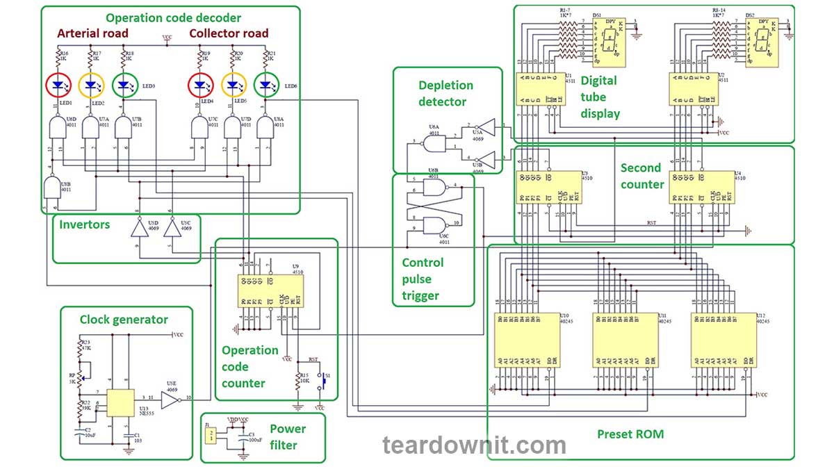
The clock generator in the lower-left corner is a standard 555 timer configured as an astable multivibrator. Its frequency can be adjusted with a potentiometer. For this project, we want one pulse per second.
The seconds counter counts down instead of up, because the display needs to show how many seconds remain before traffic can enter the intersection—or how long drivers still have to wait for the green light.
The digital display is based on the same programmable down-counter design used in the earlier article about counting pulses. We use individual seven-segment LED displays and CD4511 BCD-to-seven-segment decoder/drivers.
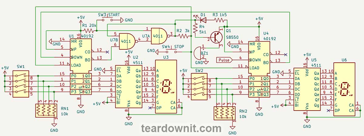
Each of the two decimal digits is stored as four binary bits, giving us a total of eight bits, or one byte.
Binary-coded decimal (BCD) differs from ordinary binary because each 4-bit nibble can represent only decimal values from 0 = 0000b through 9 = 1001b. A regular binary nibble, by contrast, can represent values up to 15 = 1111b.
When we want to represent a full 4-bit binary value with a single symbol, we use hexadecimal notation. Along with the digits 0 through 9, hexadecimal uses the letters A through F for values 10 through 15.
This time, we use a CD4510 as our reversible BCD counter. Unlike the CD40192, which has separate inputs for counting up and down, the CD4510 uses a single UP/DOWN control input.
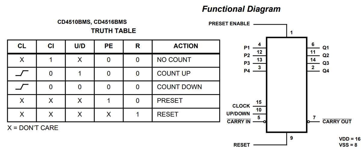
When this input is logic high, the counter increments on each clock pulse. When it is logic low, the counter decrements.
That is especially convenient when working with devices such as rotary encoders. I’ll cover how to detect an encoder’s direction of rotation in a future article.
Like the CD40192, the CD4510 also supports preset loading. In the electronic stopwatch project, we manually entered the BCD starting value for the countdown with DIP switches.
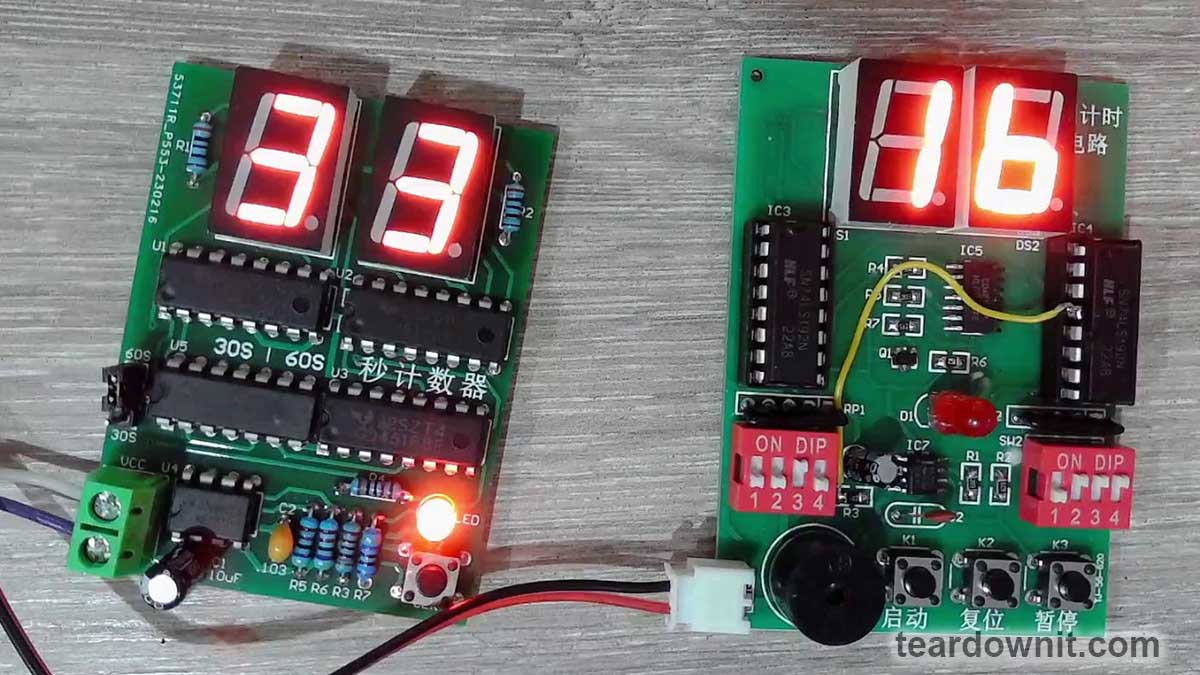
Unlike that stopwatch, however, this traffic light controller is fully automatic. The required countdown values are stored in a hardwired ROM-like circuit.
What values do we need? Only three numbers are required for the four-stage traffic light sequence.
#1 (00). The arterial road has a green light, while the collector road has a red light. Duration: 30 seconds.
#2 (01). The arterial road has a yellow light, while the collector road has a flashing red light. Duration: 5 seconds.
#3 (10). The arterial road has a red light, while the collector road has a green light. Duration: 20 seconds.
#4 (11). The arterial road has a flashing red light, while the collector road has a yellow light. Duration: 5 seconds.
So we only need to store three values: 30, 20, and 5. In BCD, those are 00110000, 00100000, and 00000101.
To do that, we use three identical 74LS245 octal bus transceivers with 3-state outputs. They are configured to transfer data from the A side to the B bus.
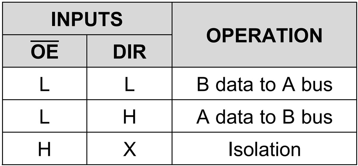
Any bit that needs to be logic 1 is tied to the positive supply rail, while any bit that needs to be logic 0 is tied to ground.
Normally, the outputs of all three transceivers remain in their high-impedance state. Only the transceiver containing the value needed for the current traffic-light phase is enabled.
When the arterial road gets a green light, the bus must carry 30. When the collector road gets a green light, it must carry 20. During the other two phases—when one road has a yellow light and the other has a flashing red light—the bus carries 5.
Once both countdown counters reach zero, a zero detector sets the control-pulse flip-flop, which is built from two cross-coupled NAND gates.
Counters U3 and U4 then switch into data-load mode, load the new countdown value from the bus, and stay in that mode until the next one-second pulse resets the control-pulse flip-flop.
At the same time, the traffic light advances to the next phase because the control-pulse flip-flop also sends a pulse to the opcode counter U9.
We use another CD4510 here, but this counter only needs four states: 0 = 0000b through 3 = 0011b.
When the count reaches 4 = 0100b, Q2 goes high and switches the counter into preset-load mode. Since inputs P0–P3 are tied to ground, the counter loads 0000 and starts the sequence over again.
Signals Q0 and Q1 are fed to the opcode decoder both directly and through inverters U5C and U5D.
Inverters are common in decoder circuits because the logic often needs access to both the true and complemented versions of each input bit.
For example, a typical 3-to-8 decoder circuit from the 74HC138 datasheet uses both the direct and inverted forms of its inputs.
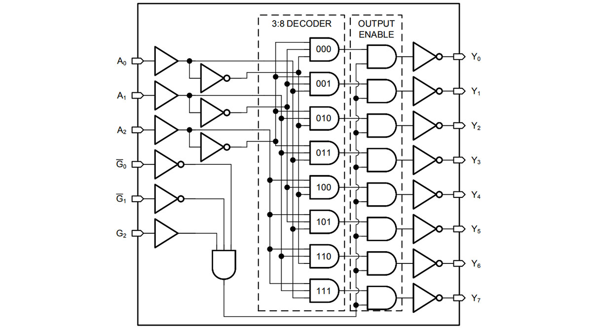
The next stage uses AND or NAND gates wired to implement the required truth table. For this traffic light, the logic is:
Arterial road: green = 00, yellow = 01, red = 10 or 11, or 1X.
Collector road: green = 10, yellow = 11, red = 00 or 01, or 0X.
Flashing-red condition: 01 or 11, or X1.
This gives us the opcode decoder. NAND gate U8B generates the flashing-red signal.
In this simplified design, we have essentially built a microprogrammed state machine that reproduces several basic processor-like functions, just without an arithmetic logic unit (ALU).
The opcodes occur in sequence, and the instruction address is the same as the opcode. That means the opcode counter doubles as both the program counter and the mechanism that steps through the program.
