How does binary logic work? Latch registers with tri-state outputs
We thank you for your attention!
Latch registers are a crucial part of any microcontroller, without which it simply couldn't function. Understanding latches can help both in programming microcontrollers and in making devices with discrete microchips, which is what we'll be doing today.
When working with an ADC, a pulse counter, or some interface, you get changing data. At some point, you need to freeze that data for display or to pass it to a program.
Remember when we built an electronic frequency counter using a couple of three-digit MC14553B BCD counters?

The working algorithm was pretty simple. The counters are reset to zero, then the input signal pulses are counted for one second, giving the number of oscillations per second, or the frequency in hertz. The result is then latched and displayed for three and a half seconds.
This algorithm was implemented in ten half-second stages, timed by a CD4017 counter-decoder. Commands were sent to the MC14553B counters' control inputs as logical ones from the CD4017 outputs through diodes.

This method has its drawbacks. The counter reset phase lasts a whole half-second when a short pulse would suffice. During this time, the seven-segment displays show absolutely nothing.
Next, for a second, the numbers flash on the displays as the pulses are being counted. Only after this do you see the final frequency in hertz before the displays go blank and the process starts over.
It's visual but impractical. Real frequency counters and other digital measuring instruments show a periodically updated final measurement result, while intermediate data is stored and processed in hidden registers.
The MC14553B counter allows for such an advanced algorithm. Its MASTER RESET (MR) input resets only the counters and the scanner register for dynamic display, leaving the four-digit latches untouched.
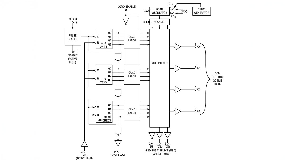
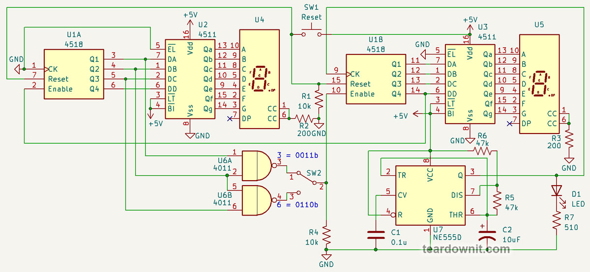
Our today's frequency counter, unlike the previous one, is not built on a counter with built-in latches but on four trusty four-digit counters, the CD4518, and two 74HC374 eight-bit latches as separate chips.

Remember the basic electronic stopwatch? At the top of our frequency counter's circuit, we see the same setup, with the only difference being between the CD4518 and the CD4511 counter-decoders, we have the 74HC374 latches.
A latch register is just an array of synchronous D-type flip-flops. Data at their outputs is held until the next clock pulse.
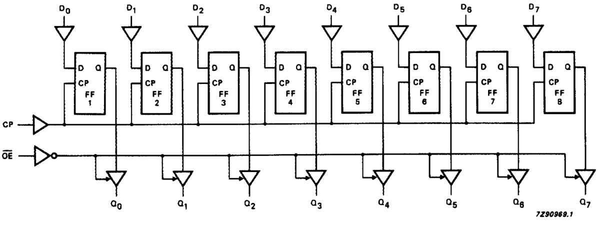
That means a logical zero switches to a logical one. At this moment, the latches read the input data, pass it to the outputs, and hold it until the next clock pulse.
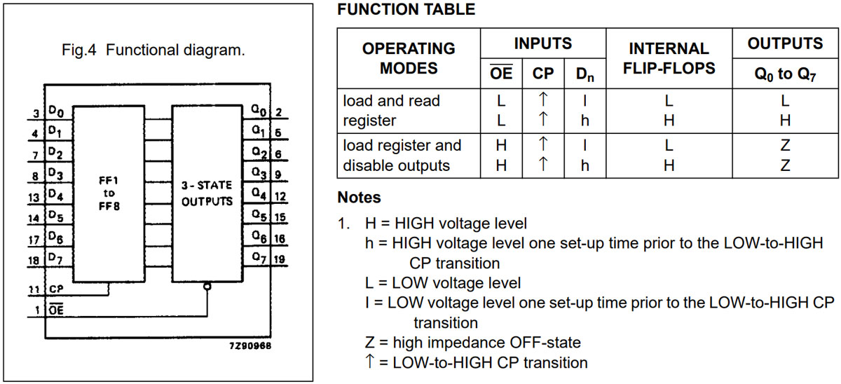
Like microcontroller ports, the eight-bit 74HC374 latch has tri-state outputs. Besides logical zero and one, meaning high and low voltage levels, the output buffer can disconnect itself and go into a high-impedance state.
In microcontrollers, this third state usually means switching a pin from output to input mode. Microcontrollers allow separate pin control, but with the 74HC374 chip, you can enable or disable the entire port.
Now that we know how a latch works, let's look at our frequency counter's algorithm.
The input signal is amplified by an operational amplifier, clipped by a Zener diode, and fed into the Schmitt trigger U12A.
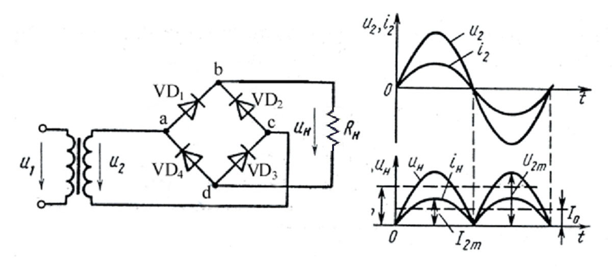
The frequency counter is powered by a transformer power supply. This DIY kit from Amazon was originally designed in China, so it's meant for a 50 Hz power grid. To use it here in the US, you need to multiply the measured frequency value by 6/5, or 1.2.
The thing is, pulses from diodes D1 and D4 go to the Schmitt trigger U12B and are used as the reference frequency, 100 Hz in China or 120 Hz in the United States.
Why is the pulse frequency twice that of the power grid? Because the rectifiers in the frequency counter are full-wave, not half-wave.
Full-wave rectifiers are often used in guitar octave pedals to double the electric guitar signal frequency.
The diodes in the frequency counter form two half-bridges, not a full bridge, designed to work with the transformer's center-tapped secondary winding. One half-bridge powers the device, while the other provides the reference frequency signal.
The U1 chip is a seven-bit binary counter, CD4024. And U14A is an AND gate, outputting a logical one when U1 Q3, Q6, and Q7 are logical ones. That’s when the counter reaches 100, as 2 to the power of 3 is 8, 2 to the power of 6 is 32, and 2 to the power of 7 is 64. Adding these gives 100.
To adjust the frequency counter for the US power grid, you need to set the logic gate to trigger at 120 instead of 100. 120 = 1111000b. So, we need a four-input AND gate connected to Q7, Q6, Q5, and Q4. It can be made with a three-input AND gate and a two-input one.
The AND gate U14C is used to reset the U1 counter with the 100 Hz or 120 Hz pulse, respectively, on the 101st or 121st count. Then the count starts over.
So, the flip-flop U2A will be toggled once per second or once every five sixths of a second if you don't modify the circuit for a 60 Hz power grid.
When U2A is at logical one, clock pulses of the measured frequency will go to the U5B counter via NAND gate U3B.
When U2A switches to logical zero, the clock pulse makes the U6 and U7 latches read measured values from the frequency pulse counter. The seven-segment displays update.
The following 100 Hz or 120 Hz pulse resets the pulse counters via AND gate U14B without affecting the display readings. And then the cycle repeats.
That's how our improved frequency counter works, with 15 chips, including a power regulator. You can see it in action and the assembly process in the video.