Matrix Connection: Few Pins, Many Options
We thank you for your attention!

4+4=8, 4×4=16. It often happens that a microcontroller or other chip has too few pins. You can use a more complex and expensive microcontroller, or you can multiplex the pins. Today I will describe one of the ways to do this.
In previous posts, we have already talked about decoders and demultiplexers, as well as shift registers.
In the first case, an n-bit binary number can point to one of the decoder outputs, the number of which is equal to two to the power of n.
For example, the 74HC138 3:8 demultiplexer chip allows you to light up eight LEDs or turn on eight relays using only three microcontroller pins or three communication wires between devices.
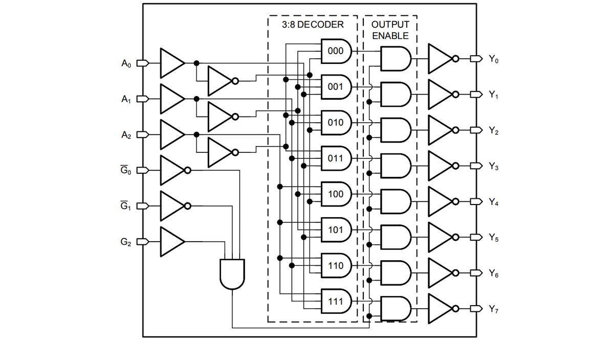
However, this scheme does not allow activating several outputs simultaneously. In the case of LEDs, we can take advantage of the persistence of human vision and constantly send different numbers to the inputs of the 74HC138. If the frequency of numbers changing exceeds 24 hertz, then it will seem to us that from 0 to 8 LEDs are lit simultaneously and continuously.
It should be noted that the more LEDs are used, the dimmer each of them will be. Although in some cases this is a good thing, the consistency of the overall brightness means that when more LEDs are turned on, they will not be blinding.
It is also possible to turn on several relays simultaneously through a decoder, although it is more difficult. Timing circuits similar to those used in running lights with slowly dimming LEDs will be required.

Thanks to diodes with RC circuits at the bases of transistors, relay coils connected instead of LEDs will switch off not at the same moment as the signal disappears from the decoder output but after a certain period of time.
If you keep the capacitor charged by periodically applying the corresponding number to the decoder input, the relay remains on. If you stop transmitting this number, the relay will turn off.
This is very similar to the operation of the Williams-Kilburn tube, one of the first types of computer memory in history. The electron beam scanned the cathode-ray tube screen, just like a television.

To turn the indicator into a storage device, engineers simply added a matrix of electrodes onto the screen and synchronized the modulation of the beam with the scanning of this matrix. Those areas of the glass where the electrons hit acquired a charge that would fade if not renewed.
Of course, this was not a fast memory by any stretch. And controlling a relay via an RC chain is also not fast. However, it fits a number of applications.
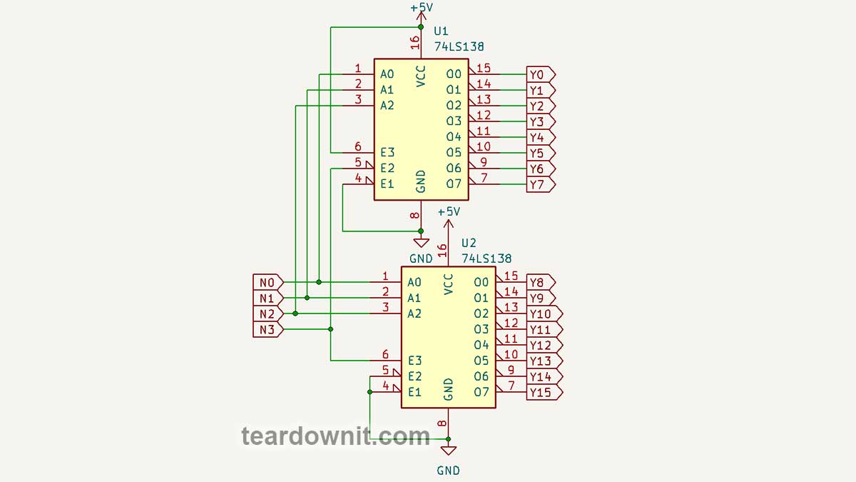
Each additional wire or microcontroller pin doubles the capacity of the demultiplexer. For example, 4 bits give 16 outputs. But the required number of decoder chips also doubles. For 4:16 you need two 3:8 chips, for 5:32 you need four, and for 6:64 as many as eight, and so on.
But the shift register allows you to transmit or read practically an unlimited number of binary bits using only three wires: one for data, one for clocking, and one for register latching.

Therefore, when paired with microcontrollers, to expand the number of pins, shift registers are most often used rather than demultiplexers.
Two CD4017 decimal counter-decoders have 2×10=20 outputs. But if you make a matrix where one chip scans the rows and the second the columns, you get 10×10=100. Or 9×9=81, as done in this matrix LED effect.

The same design is used in an electronic timer, where 6×10=60 LEDs are placed around the circumference of the dial and serve as the second hand.
As you can see, the matrix is not necessarily square or rectangular. It can be stretched into a line or closed into a circle, and in general, its elements can be arranged in the shape you need.

The decade counter U2 receives timing signals with a frequency of 1 hertz from the generator on the 555 timer. Using switch SW1, you can switch the chip to 'disable counting' mode, which means a pause in the stopwatch operation.
U2 counts to ten (from Q0 to Q9) and transmits the CARRY-OUT signal to the clock input of U1. Note that CARRY-OUT goes to logical zero when the counter has counted to Q5, and to logical one at the moment of overflow, when Q0 is activated again after Q9.

The CD4017 chip reacts just to the transition from low to high, so U1 will turn on the next row of LEDs exactly when U2 has turned off column Q9 and turned on Q0.
The active voltage level at the outputs Q0..Q9 of the CD4017 counter is high, and the current in the LED should flow from plus to minus, from anode to cathode, in the direction of the arrow. Therefore, the signals from the U2 outputs are inverted by the U3 CD4069 chip.
This chip contains six logic inverters. To count 60=10×6 seconds, we just need 6 lines of 10 LEDs. On the diagram, they look like rows and columns, but on the board, they are placed around the circumference of the dial.
After a minute has passed and Q2 has counted to Q6, transistor Q1 opens through resistor R2, performing two actions in our circuit.
First, it charges the capacitor C1, the voltage across which turns on transistor Q2 through resistor R3. This is exactly the same scheme that we've discussed above.
While C1 is discharging, the BZ1 buzzer will beep, not continuously but in 1 hertz pulses, since the positive terminal of BZ1 is connected not to the positive power supply terminal but to the output of the second pulse generator.
An asymmetrical flip-flop is constructed on transistors Q3 and Q4. A logical one from capacitor C1 through diode D1 and resistor R4, or from the power supply positive through R5 and button SW3, sets the flip-flop to one, which goes to the reset input of both counters, stopping the counting and resetting them to zero.
The diode is needed so that the buzzer is triggered only at the end of the count, not when the STOP button is pressed or a logical one appears at the output of the trigger through resistor R6, which latches the trigger into a high- or low-level state.
Button SW2 resets the trigger and starts the second count. If you made a multi-position switch that allowed you to choose which of the Q1..Q6 pins to connect R2 to, the timer could count not only up to 60 but also up to 10, 20, 30, 40, and 50 seconds.
And the last circuit for today is an RGB running light. Here IC1 is the familiar CD4060 binary counter, and 74HC138 is a 3:8 decoder that lights up one of the eight LEDs, LED1..LED8.

These are RGB LEDs, and the light color will depend on the state of the outputs Q8–Q10 of the IC1 chip.
- 000: white; all channels are on
- 001: blue-green
- 010: magenta; blue plus red
- 011: blue
- 100: yellow; red plus green
- 101: green
- 110: red
- 111: LEDs do not light up
As you can see, even to control RGB LEDs, it is not at all necessary to use a microcontroller. With two simple chips and three transistors, you can create the beautiful effect of a running, color-changing light.